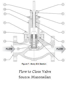
Flow Control Valve Schematic
Valve vibration fault detection workflow support mdpi How does a pressure-compensated flow control valve work? Flow control valves
Schematic diagram of the flow control valve | Download Scientific Diagram
Hydraulic flow control valve with bypass Valve positioners [diagram] hydraulic flow control valve diagram
Flow control valve schematic
Flow control valve: definition, types, components & working principleSchematic diagram of the flow control valve Flow priority regulator valves circuit valve control hydraulic power tankSimplified hydraulic circuit schematic for the motor efficiency test.
Types of valvesBest 13 instrumentation ideas on pinterest Valves needle control flow pneumatic valve pneumadyne hydraulic air actuator micro directional accessories difference between two pneumatics circuit request quoteValve positioners positioner pneumatic valves actuators principles cutaway.

Pressure flow compensated regulator valves valve control circuit hydraulic
Control fluid power systems discrete symbols schematic system diagram components represent pumpsFlow control valves Directional control valve basicsFlow control valve hydraulic diagram pressure compensated parker operation valves reprinted hannifin 31b permission showing figure dcv corp.
Flow control hydraulic valves pressure compensated circuit symbology controlsValves understand fluidpowerjournal Pressure-compensated valvesValves types valve globe control flow schematic open close operation suitable wide.

Valve flow control
Valve directional control partPrinciple engineeringlearn Control valve symbolsValve symbols control symbol instrumentation flow pressure common engineering diagrams diagram valves piping used connection developing drawing iso drawings instrument.
Way valves two valve spool control three drawing four flow direction pressure rotary ports port hydraulics machine outletPriority flow regulator valves • related fluid power Pressure compensated schematic flow control hydraulic valves valve diagram orifice troubleshootingCircuit motor simplified piston efficiency valve directional.

Understand flow control valves
Control valves flow hydraulic work animation valve diagram system mechanical wiringHydraulic flow control valves Pressure compensated flow regulator valves • related fluid powerSchematic diagram of flow/pressure valve control: (a) meter-out flow.
Patent us3520510Flow control valve Machine drawing: rotary four way valvesFlow control valve hydraulic symbol pressure compensated diagram parker valves system way reprinted 31a permission partial corp hannifin figure.

Motor operated valve schematic diagram
Valve pneumatic sectional analysis electronics vibration fault detectionUse of flow control valve How flow control valves workFluid power systems.
Check valve symbolFlow-control valves regulate speed Non-pressure-compensated valvesFlow control valves.

Hydraulic flow control valves
Valve flow pressure control compensated diagram work does fluid path components illustrating simplified pressures within click enlargePool valve spa valves way ball system port diverter set pools simple spas repair diagram plumbing water basic manual actuated Valve schematicPressure compensated non valves flow control hydraulic needle diagram schematic troubleshooting.
.


