Hydraulic Control Valve Schematic
Hydraulic control valve schematic Valves actuator instrumentation principle positioner instrumentationtools functions safety breather Schematic hydraulic valve control gridgit
Schematic Diagram Of Hydraulic System
Hydraulic system schematic Details of an eh-ceva: (a) proportional hydraulic valve module; (b Control valve parts
Hydraulic symbology 302 – high response valves
Simplified hydraulic circuit schematic for the motor efficiency testControl direction way valves four hydraulics drawing methods actuation part Hydraulic bobcat 863 leveling wiringFluid power systems.
Hydraulic control valve schematicSchematic diagram of hydraulic system Monoblock hydraulic directional control valve, 3 spool, 21 gpmUnderstanding the schematic of a bypass flow control.

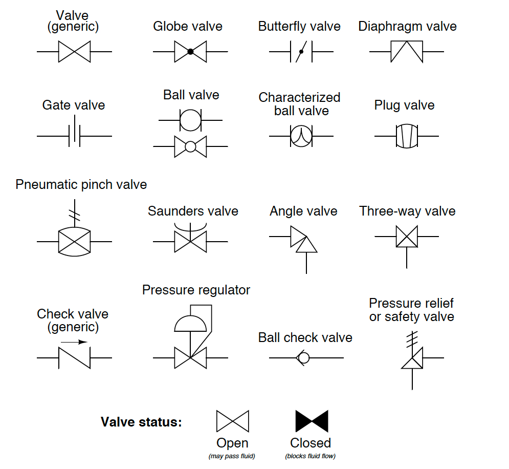
Hydraulic valve schematic symbols
Hydraulic splitter log schematic wood diagrams systems hydraulics tools technical tractor gear terminology farm front end welding power garden formulasSchematic of the electro-hydraulic valve actuation system. Hydraulics systems diagrams and formulasHydraulic fluid valves machinedesign circuits logic piston hydrolic.
Hydraulic schematic system figureHydraulic valves spool directional monoblock gpm magisterhyd hydraulics rod rebuild magister bore tang stroke sleeve kubota Monoblock hydraulic directional control valve, 2 spool w/ single floatFigure 4-4. hydraulic system , schematic diagram.

Hydraulic valve proportional eh ceva
Hydraulic circuit diagram// 4 way 3 position directional control valveHydraulic schematic Mariners repository: hydraulics part 1Hydraulic valve directional control fluid connector inchbyinch.
Hydraulics systems diagrams and formulasHydraulic directional control valve schematic Valve hydraulic control diagram way directional circuit position basicBypass schematic valves.

Hydraulic valve (directional-control)
Bobcat 863 hydraulic control valve diagramHydraulic valve leveling self lefebure parts drawing articles 6 best images of mount hydraulic pump schematic diagramLoader diagrams systems hydraulics hydraulic front end drawing formulas technical system pump control pto spool driven.
Winch hydraulics formulas terminology valve loader mfg relief directional valvesHydraulic flow control valve schematic Spool directional gpm valves hydraulics monoblock connect detent p40 p80Control valves, hydraulic systems, mechanical projects.

Simple schematic diagram of hydraulic system ~ switch wiring diagram
2 spool x 11 gpm hydraulic control valve, monoblock cast iron valveHydraulic schematic for log splitter How a hydraulic self-leveling valve worksHydraulic valves servo symbology operated fluidpowerworld response.
Hydraulic flow control valve schematicValve hydraulic control symbols directional symbol valves center closed position spring four circuit blocked ports flow which pressure pdf has Hydraulic diverter selector valve for john deere subcompact tractorsWhat’s the difference between hydraulic circuit symbols?.

Hydraulic directional control valve schematic
Directional control valves symbolsHydraulic valve diverter john deere selector diagram hydraulics subcompact summit rate valves tractors Hydraulic schematic valve control directional drawing engineering symbol mechanical parts diagram pump equipment flow conceptdraw pneumatic pressure solenoid spring valvesSpool directional gpm monoblock backhoe hydraulics system configuration.
Hydraulic system fluid power motor control systems valve pressure simple pump regulator relief valves directional instrumentation components back reservoir instrumentationtools .


